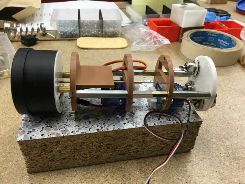
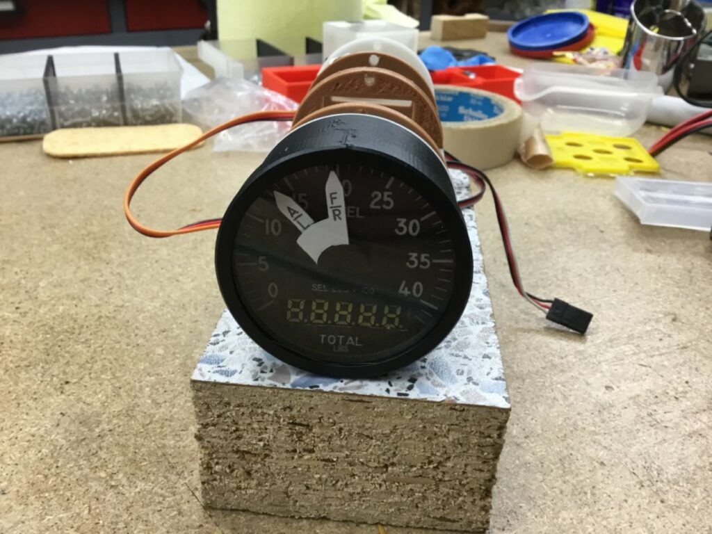
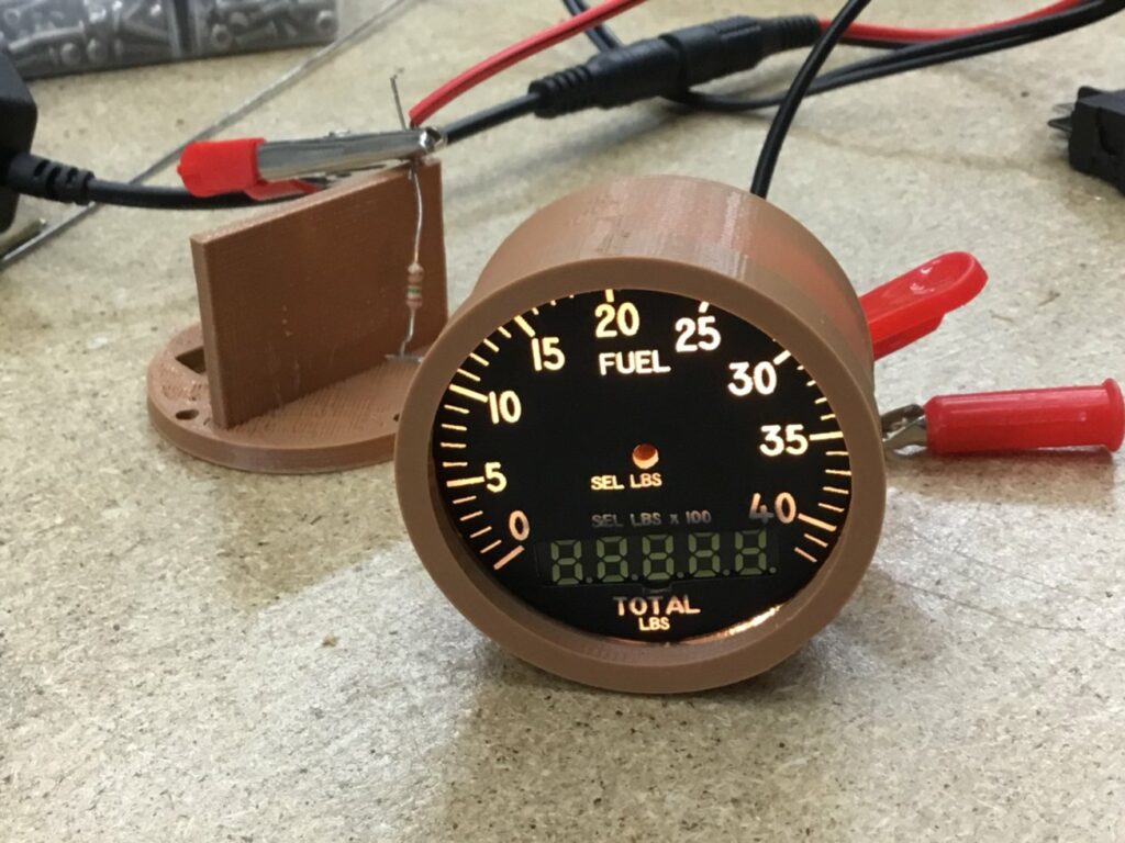
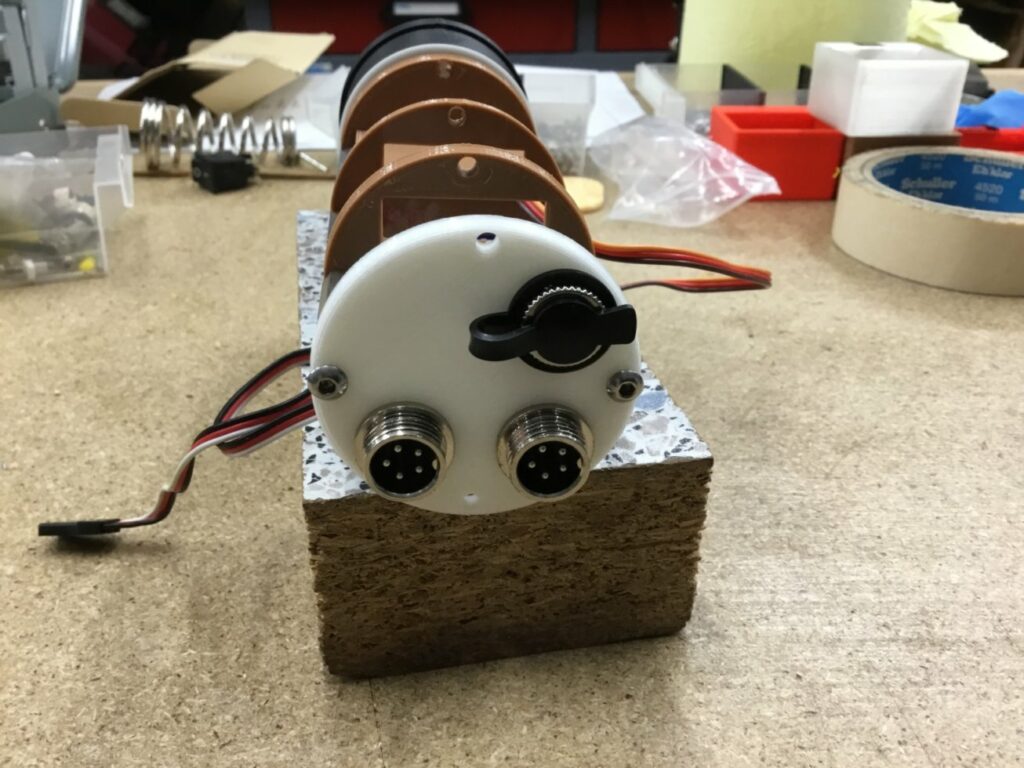
The mechanical part of the Fuel Quantity Indicator (FQI) has been done.Just like the HYDPRESS instruments the FQI consists of multiple parts connected with 3mm spacer rods.
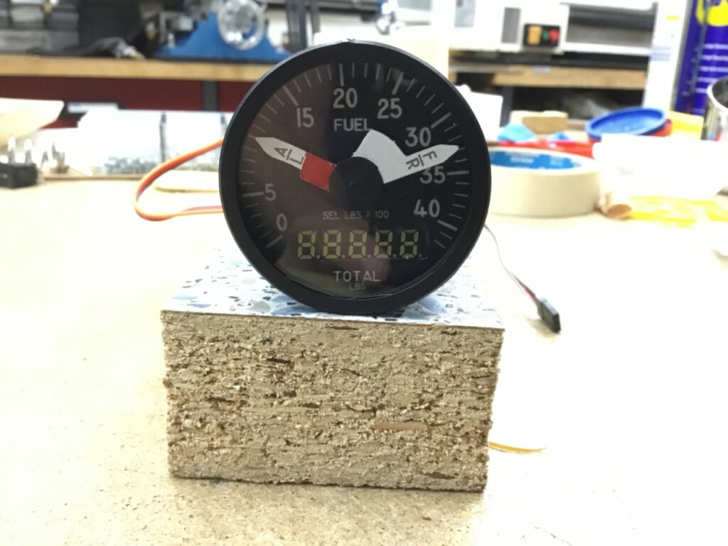
- In the frontpart (black) are the glass, a spacer, faceplate with needles and the 7-seg-display
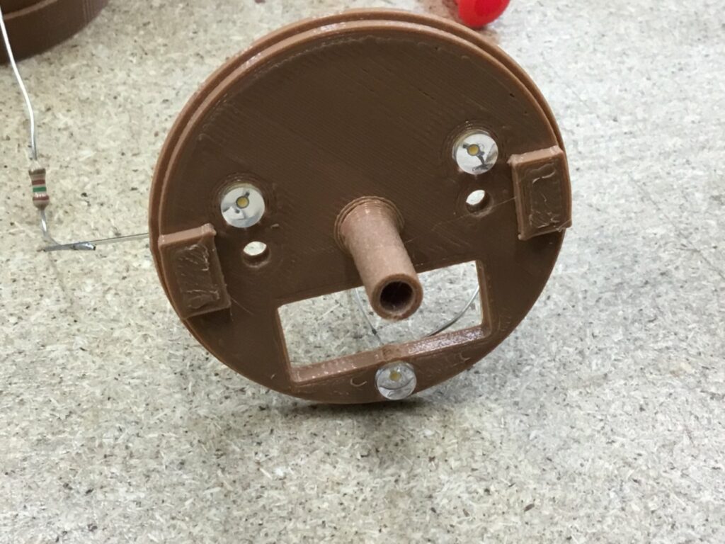
- next the LED-plate for the backlighting (white)
- next the plate to hold the MAX7219 PCB to control the 7-segs
- first servoplate (needle “A/L” – Aft/Left)
- sedonc servoplate (needle “F/R” – Front/Right)
- and at the end, as always, the connectorplate
The FQI use 2 independent needls for each tank, showing the fuel in 100lbs, the 7-seg display shows the total fuel in all tanks.
If there’s an imbalance between both tanks it will displayed by the red body of the A/L-needle which will become visible.
I planned to use about 13-15 LEDs for backlighting, but some test showed that 3 are totally sufficient.
To connect everything with the RightAUX Arduino GX-12 connectors are used, the 12V for the backlighting uses a standard barrel connector.
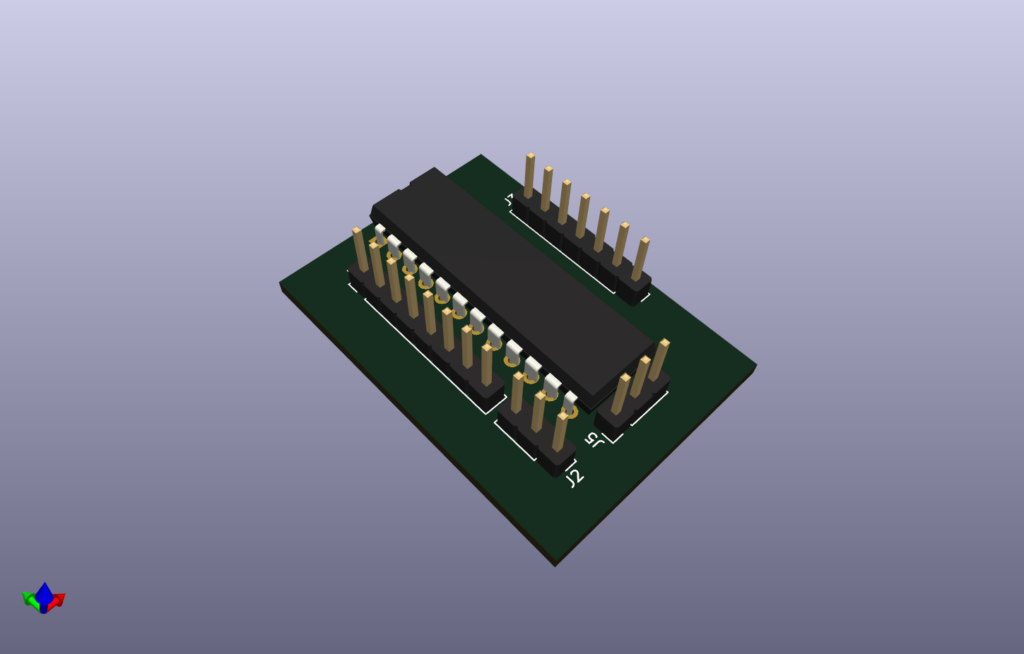
Now it’s “just” only the soldering and building the MAX7219-PCB.
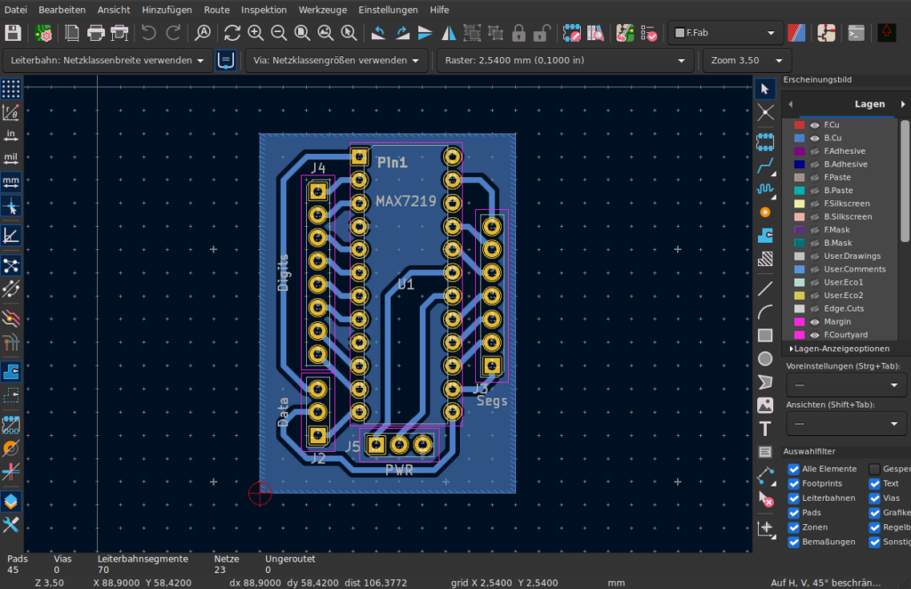
Normally I would just use some perfboard for the PCB, since it’s so simple. But because I’m planning to do more complex PCBs through isolation routing on my CNC in the future, this makes for a really nice test procjet.
So I designed everything in KiCAD and use Flatcam to create the GCode for the router.

