Phase 2 – Prototyping
After finishing most of the design work I started with programming the firmware and building a first prototype out of Plywood.
Hardware
Building the prototype is not all too complicated.
First I print out the 1:1 plan of the wheel
Since 320mm diameter is bigger than my DINA4-printer can handle, I print it on two sheets and glue them to the plywood board.

Next I drill out the holes for the buttons, switches and rotaries.

Finally I cut out everything. In plywood I use a fret saw, when doing the same in aluminium, I’m using a jig saw with a metal blade.

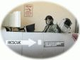
After mounting all the buttons and switches and adding the grips, I can finally test the reachability of all the buttons and I must say, I’m very satisfied with it.
All 3d-printed parts are printed very fragile, with only 1 top/bottom layer, 1 outer shell and 5% infill, so I don’t waste too much filament, if it doesn’t fit like intended.

Firmware
It’s hard to show programming in pictures 🙂 but I have a short video of the configuration management part.
The wheel will be able to save up to >200 configurations, but I limited to 10 at the moment.
Each configuration has the following parameters:
- BitePoint On/Off:
– Off: Both clutch paddles will be seen as 2 seperate analogue axis of the joystick
– On: Only one axis of the joystick will be used as clutch axis, with a bit point mode, where the 2nd paddle uses it’s whole way for just a little amount of clutch travel. - BitePoint Value:
Value in percent, where the bitepoint is located. A good video description how to set it, is available from Fanatec. - 12Pos Mode:
– Const: each position of the 12 position rotary switch will keep the according joystick button pressed, as long as it is selected (12 buttons per switch).
– Pulse: each position will send a small on/off pulse of the corresponding joystick button (12 buttons per switch).
– Enc: Encoder mode, turning the rotary switch left/right will send an on/off pulse of the corresponding joystick button (2 buttons per switch).
To enter configuration mode, I just have to press&hold both 2 funkyswitch buttons for 500ms, same to leave it again. Configuration is stored in EEPROM of the Arduino when leaving the menu.
Hello mate. I really love your idea of all the electronics on your wheel. I really want to know more about how you design and build this wheel, taking in special consideration all the code that you use. Regards!
Hi, Denis!
Progress on the wheel is quite slow or better said, on hold.
Once it’s going on again, I will do another post about it, of course.
All the code is self written, at the moment I’m not sure if I’m going to release is publicly…
greetings
michi
Oh, ok mate. It will be nice to see it working in the future. About the code, I think the whole DIY community will be amazed if you release it. I understand as well your decision on not release it if you don’t want to. But thanks on the reply.
Best regards!
Sorry for the late reply.
At the moment the code is way too ugly to be released (and quite special to my custom hardware).
But never say never 😉
That’s something great to hear mate! I know that is something very specific, but I’m interested on do something very similar to what you have achived.
Best regards!!