The RIGHTAUX is getting some light 🙂
I’m trying to finish the whole right side of the pit at once, since it will be hard to get to everything once it’s assembled – the right side will be very close to the wall.
So additionaly to the structure I want to do all of the instruments on the RAUX, since it would be a bit tedious to install everything afterwards.
Replacing all the panels can be done later, since the cables will be already inside the console.
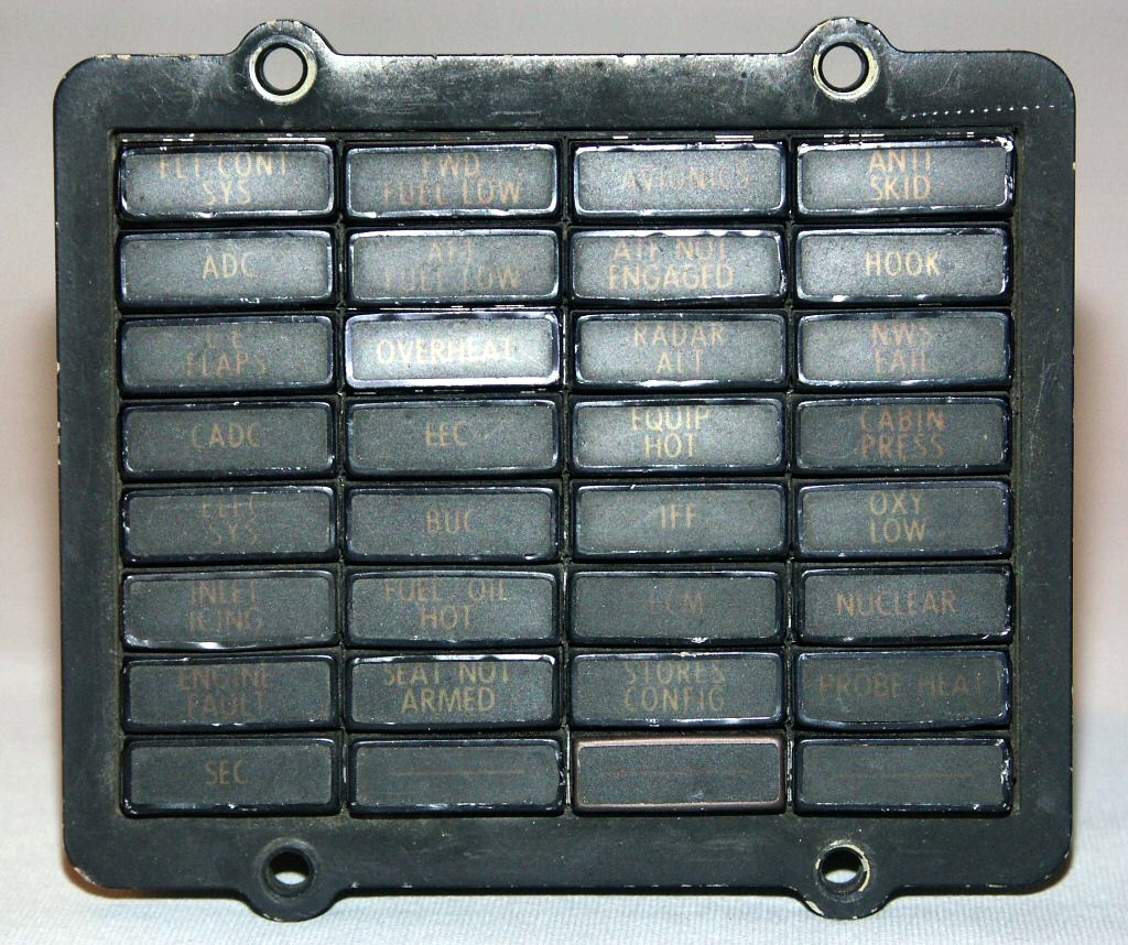
The CautionPanel has been on my ToDoList quite some time now. I never managed to get things started, but finally it’s done.
My first implementation of the panel in 2001 was quite rudimentary 🙂 (and not functional)
For the new CP I decided to get as close to the original as possible, since Martin Schmitt at xflight.de has a very detailed info page with measurements and pictures of the real deal.
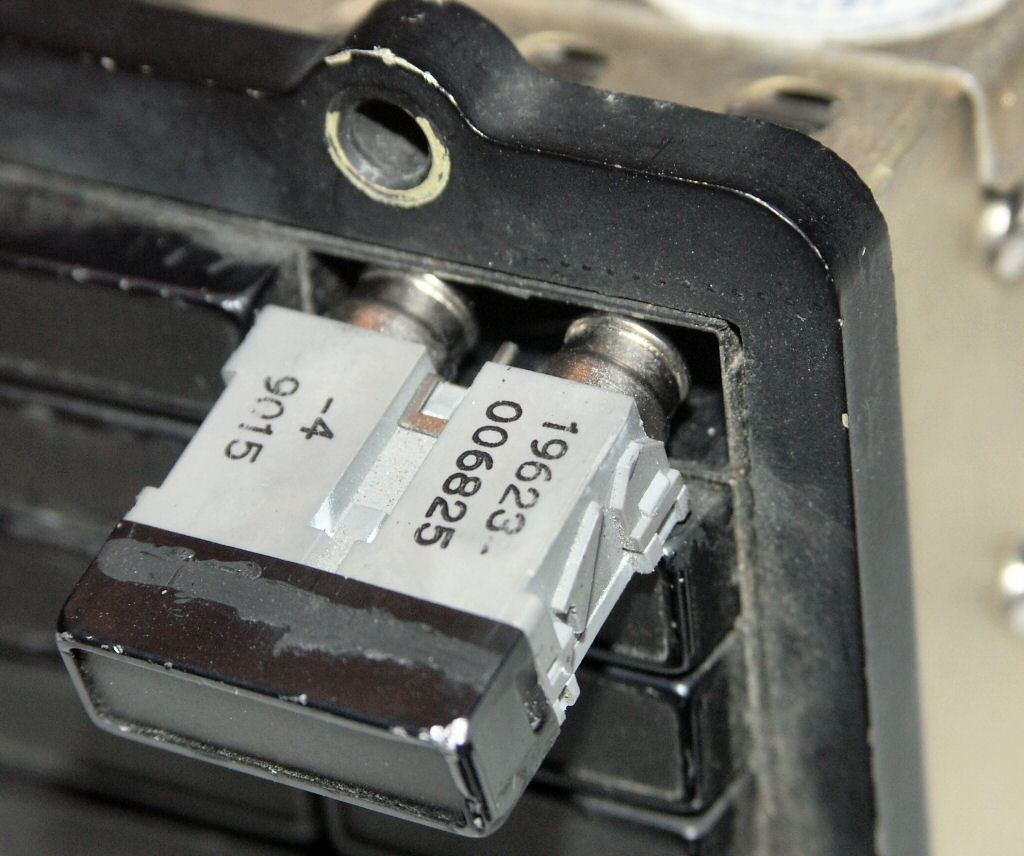
The indicators of the real CP can be pulled out from the front to change the bulbs and the lense caps and I wanted to build mine very close to that.
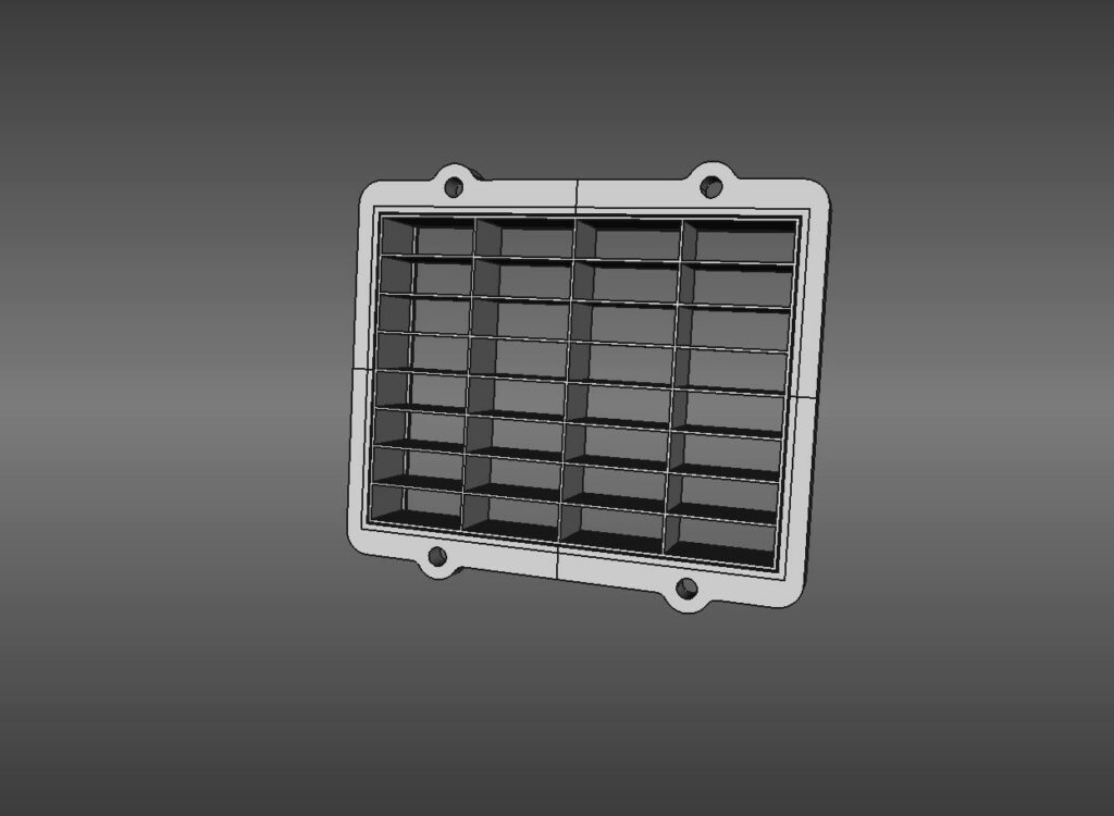
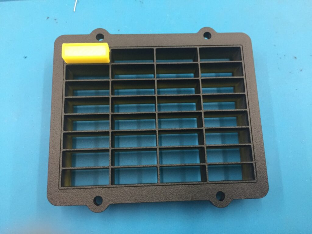
So as always I spent quite a bit of time in FreeCAD, designing the frame and lenses optimized for 3D printing.
The frame was designed including the inside walls and the idea to mount a plate with the LEDs and the MM5451 at the back.
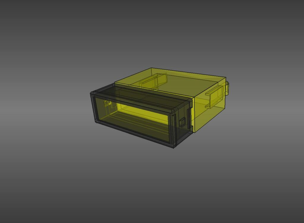
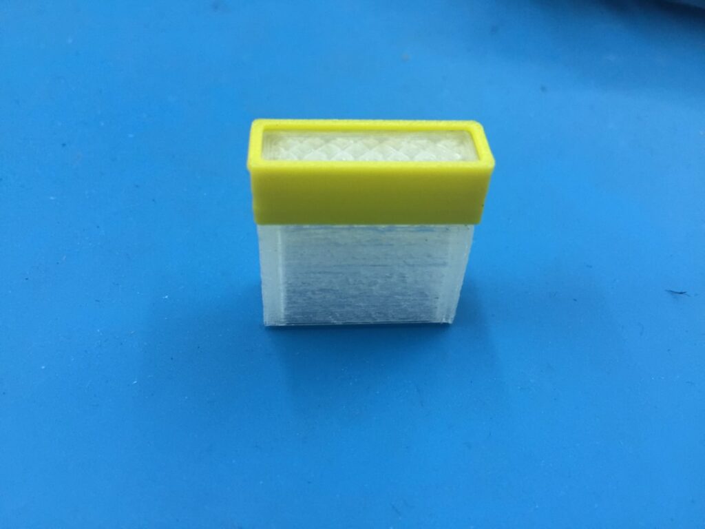
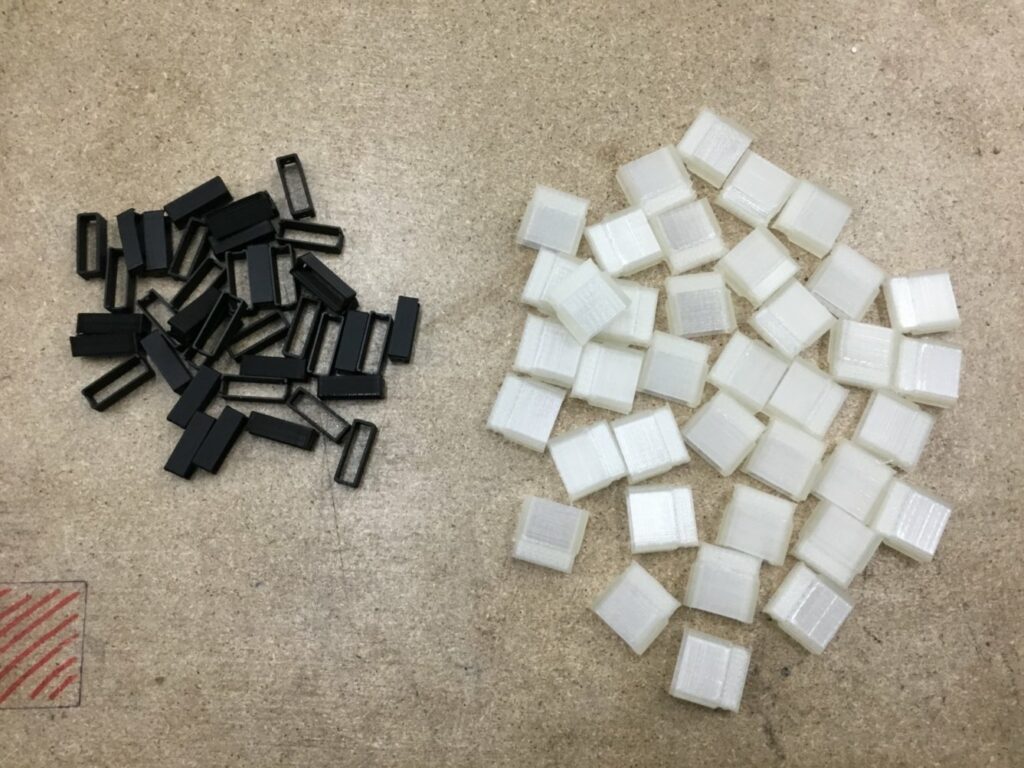
The lenses consist of 2 parts, the lens body (yellow) and the cap (black), which mounts onto the body using 2 small clips on each side but they won’t hold the LEDs inside, those will be mounted on a PCB behind the backplate.
To mount the lens to the backplate I added also 2 clips at the back to keep them from falling out the front.
The backplate itself slides into slots in the back of the frame.
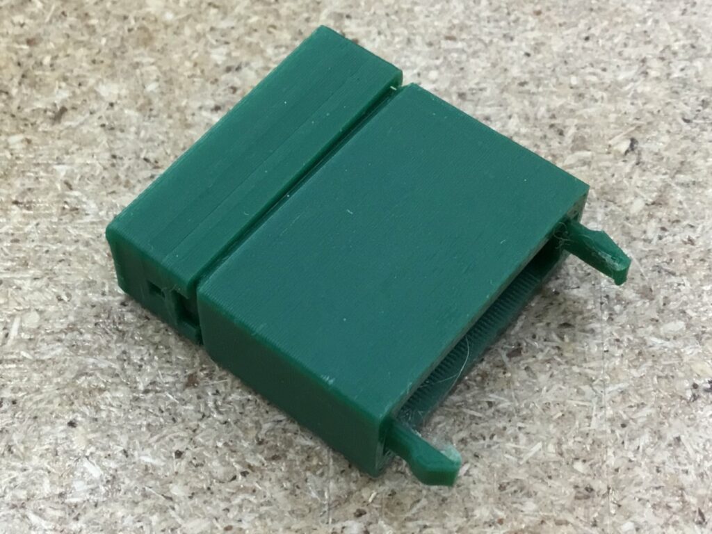
After the design phase there’s the prototyping phase where I print some test pieces of the parts I just designed, to check the sizing and fitting between them.
On this first try I got the tolerances between lenscap and lensbody too tight and the cap broke when clipping it to the body. After I adjusted those measurements, everything worked out pretty fine.
The fitting of the lens inside the frame was perfect, but the small clips tended to break. I designed it to be printed with the front on the printbed (to make it perfectly flat) but that meant the clips would could break along the printlayers.
Since the fit inside the frame was very snug and nothing moved, I decided to remove the clips from the design and go with a friction fit between frame and lenses.
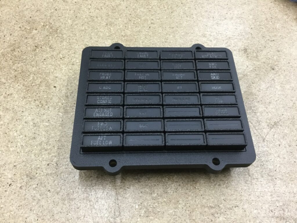
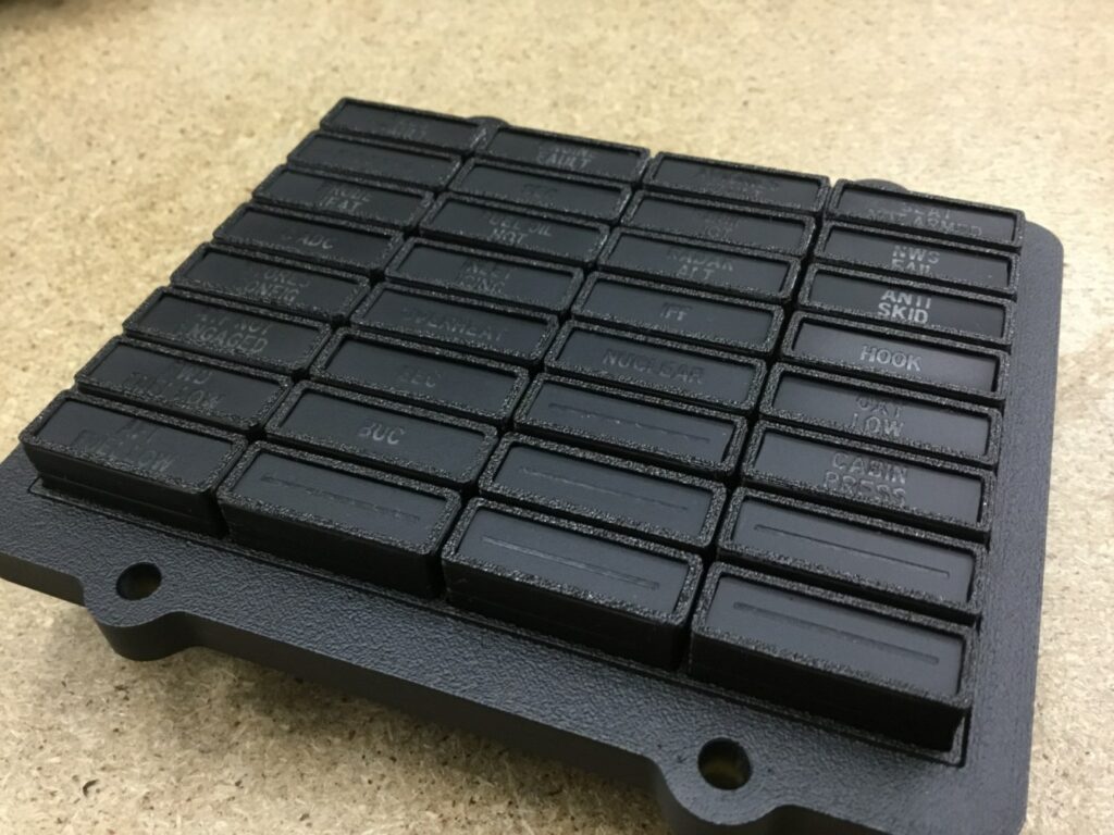
After printing and painting the frame I was very satisfied.
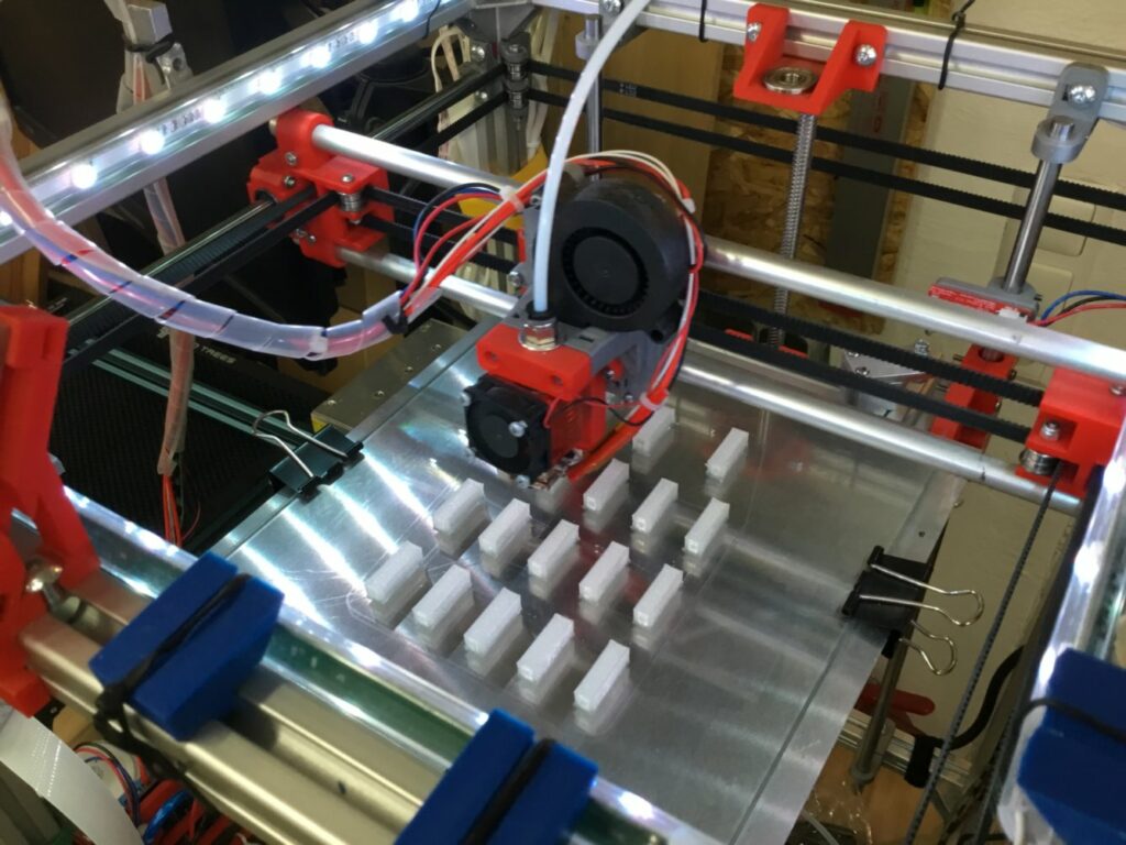
The textured surface of the panel is created by the PEI-sheet on my new 3D printer and I really like the look of it.
The next ToDo was to check, if my plan of backlighting the lenses would work out.
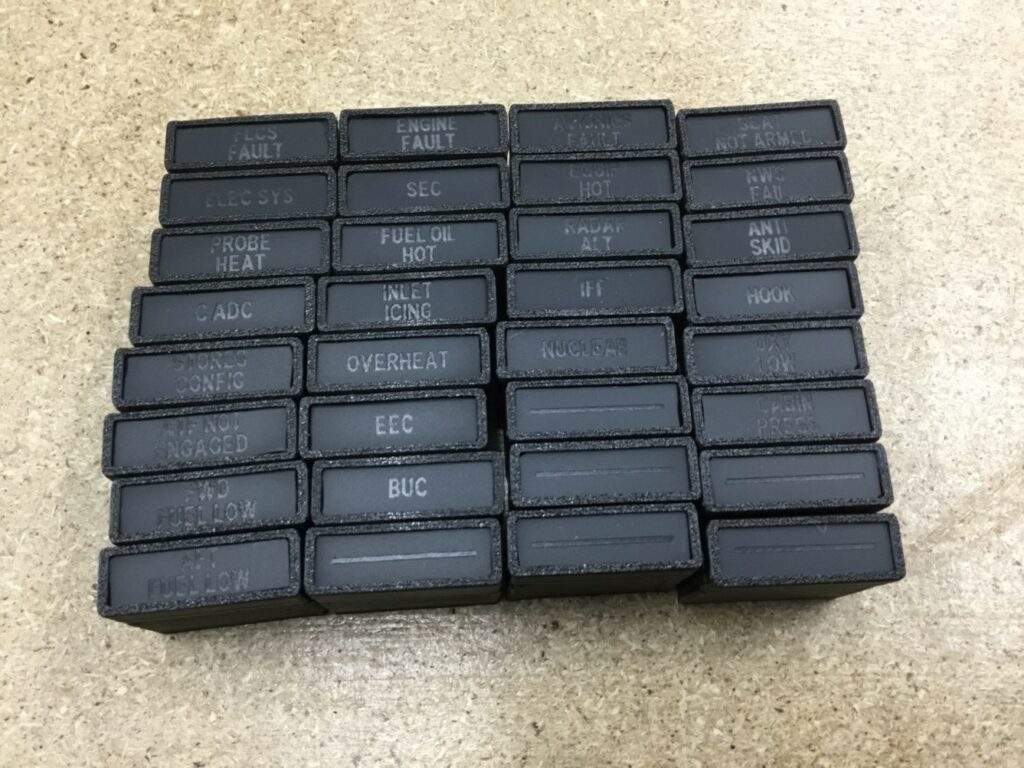
Like with my panels and instruments the plan was to print the whole lens with transparent PLA, spraypaint everything matte black and then laser the lettering onto the front.
I wanted to use one high brightness wide angle 5mm LEDs per lens but wasn’t sure if the light diffusion would be ok or if I would have to add a seperate diffusor to the lens.
After some test prints I found the perfect CAD design and print settings to diffuse the light enough, preventing bright spots in the middle and let the letter light up perfectly.
After all those satisfying tests it was time to go into production mode 🙂
Painting all those lenses was NOT FUN, but seeing all lenses finished at the end makes up for all the work.
It now looks very close to the real panel and I’m really, really satisfied, how it turned out.
The front of the panel was great, now it was on to do the backside.
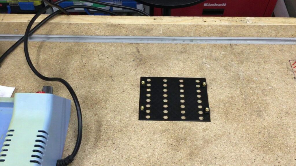
After some tries I designed the backplate to have a hole for each LED and clamps would screw into the inserts to hold the PCB in place.
The PCB itself is very simple, since it’s just the holes for the LEDs in the correct place and seperate solderpads for anode and kathode of the LEDs.
Sadly my workholding on the milling process was quite unregular (and sometimes in the air) so I had to recut some pads with a cutter knive.
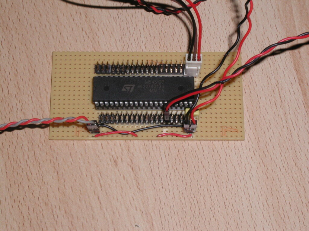
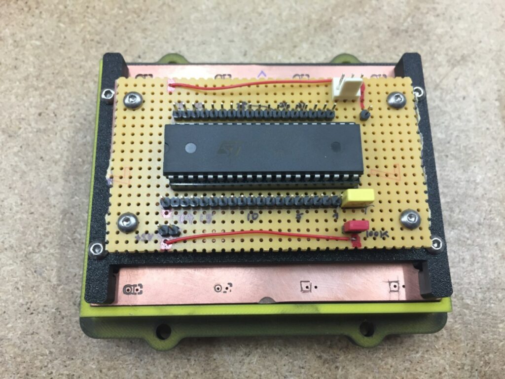
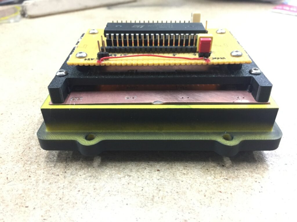
To control the LEDs I’m using an MM5451 control chip PCB I had done quite some years ago which will be piggybacked on the PCB holding parts.
The chip is controlled by my BMSAIT-RightAux Controller, an Arduino Nano.
The CPs backside when assembled:
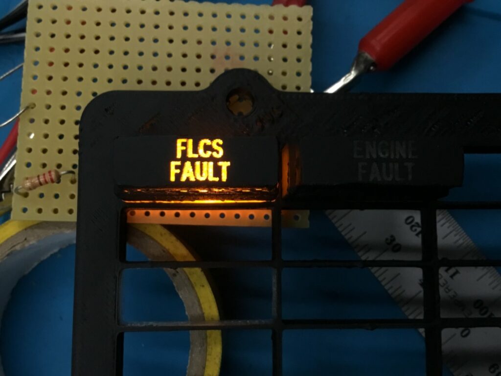
I still have to solder all the LEDs to the connector, but I managed to add some of them to the MM5451 and run a test:
Next on the ToDo List is the PFD (Pilot Fault Display)


