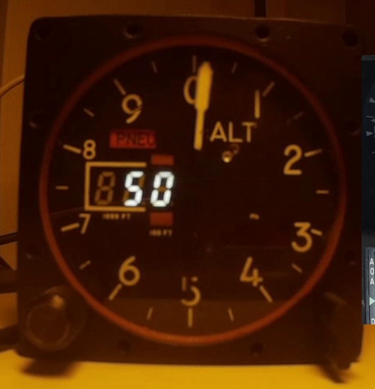
Just the baro settings display and connector plate are still missing, everything else is working fully inside the instrument.
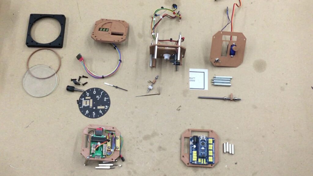
These are the parts of the Altimeter:
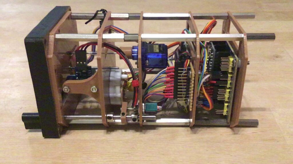
Still missing is the connector plate for the other instruments controlled by the Nano (ASI, VVI, MarkerBeacon):
– Frontplate with spacer (still to be painted black) and glass
 Since I salvaged a real altimeter I could use the real glass for my selfmade version.
If you don’t have a real altimeter ;), you could just use some acrylic or other plexiglass.
For my old instrument mockups I used 2mm Polystyrol but was really shocked, when I measured the real glass, which is about 3.5mm thick!
So my next instrument without a real glass will have 3mm acrylic at the front.
– Faceplate with needle, number plate, baro knob and installed altitude display (plate is still beta, until the missing display arrives)
 The faceplate holds one 3-digit 7-segment-display to display the altitude in 100ft and one 4-digit 7-segment to display the barometric setting. Since I couldn’t find a 4digit display small enough, I’ll use a 5-digit one and hide the last behind the number plate.
There’s also a small recess for the PNEU flag to rotate in, without touching the original numberplate.
8 2.5mm screw inserts will be put into the holes on top, bottom, left and right where the frontplate will get screwed onto.
Stepperplate with X27.168 stepper motor, zeroize sensor and needle shaft
 I’m using an X27.168 stepper motor designed for automotive purposes. It’s capable to rotate 600°/second and has a step resolution of 1080steps/revolution.
Using a 1:2 gear ration on the needleshaft, I’m capable to reach about 1200°/second which is fast enough for nearly all maneuvers the F-16 can do.
Also an encoder with push button is mounted to this plate. This controls the baro settings in BMS but also lets me adjust the needle offset to the zero position, using a special config mode which is started/ended by holding the push button down for about half a second.
 The needleshaft is supported in 2 small ball bearings, one in the stepper plate, the other on the backside of the faceplate.
– Servoplate with PNEU switch
 A common SG90 mini servo is used to control the PNEU needle. It’s fast enough, since it just has to turn 90 degrees.
The PNEU switch on the front will activate the toggleswitch with an arm on the shaft. Since it’s not used in BMS (yet), I just use it to switch the configuration mode of the Barosettings knob.
When in config mode, turning the Baroknob will adjust the needle offset if the PNEU switch is in ELEC position (normal), but increase/decrease display brightness, when in PNEU position.
– MAX7219 plate
 Instead of designing and soldering my own PCB, I salvaged a 7219-LEDArray-board I had.
All I did was to create a small breakout circuit to connect the 7-segment displays to, which I would have to do anyways.
The MAX7219 will get it’s own 5V from the connector plate, although until now it was no problem to use the 5V from the Arduino.
When all 7 displays are lit, this could draw a bit too much amps, together with the servo and the stepper, so better be safe than sorry.
– Arduino Nano plate
 Here I also used one of many Extensionshields I had, instead of making a PCB by myself.
Overall this solution takes up more space but it was much less work than soldering a PCB.
I maxed out all of the pins on the Nano to control all displays, stepper and servo motors and LEDs.
– Connector plate
 All the other instruments controlled by the Arduino will get there signals from here.
The bottom 2 Connectors are 5V/GND and the USB connector of the Nano, the top 3 are for ASI, VVI and Markerbeacon.
At the back of the plate will be a breakout board for the 5V/GND which will provide 5V to all other instruments and the MAX7219 chip inside the altimeter.
Assembly starts with the faceplate which mounts to the stepper plate while taking care of putting the needleshaft in it’s place.
After that it’s just pushing all the cables through and connecting one plate after the other until all cables are connected to the Arduino.
Finally the PNEU flag gets mounted to the servo, the number plate screwed to the faceplate and the front including glass and spacer mounts to the faceplate and we’re done.
Now the altimeter works on its own, just one USB cable coming to the PC! No breadboard, no jumper cables, it’s finally a whole unit 🙂
Software
To get all the needed data out of BMS I’m using a fantastic tool called BMSAIT.
I linked to my fork of it, but the main creator and mastermind behind this program is HummerX at github
If you want to drive your pit with DIY Arduino hardware, this is the way to go, IMHO.
As soon as the missing displays arrive, it’s a bit of 3D printing and soldering and then the altimeter can finally be called done! 🙂


Hi!
where can i buy your design?
Hi!
Sorry, no plans to sell anything, but all files are available for free on my github (link at the top right besides facebook) or makerworld (https://makerworld.com/en/@mitschi/collections)