For quite some time I wanted to build a complete GT3-style steering wheel which could be used on any wheelbase.While playing ACC, although I was able to get away with my current buttonplate quite well, I realized, there are quite a few more inputs needed.
For example, I don’t have a hatswitch on my buttonplate to operate the pitstop-settings and have to reach for my buttonbox every time.
Of course I could have just build a new buttonplate alone and save me some time, but also the grips on my P104 Limite clone are a bit slippery and a touch too big for my small hands.
Since I have quite a bit of experience building stuff, I thought “Why not build a complete steering wheel by yourself? Will be fun and in the end, I’ll have something hopefully perfectly suited to my needs”. So I began some research…
Shapewise I really like the look of the Ferrari 488 GT3 wheel the best, so I decided to take the base shape and layout of the wheel and adapt it to my needs.
After looking around the web and searching for “GT3 cockpit” and “GT3 steering wheel” images I had a final design in my mind:
- diameter should be 320mm
- frontplate will be 4mm aluminium
- grips and back housing will be 3D-printed
- 2 7-way “funkyswitches”
- 4 12-position rotary switches to adjust TC, TC2, ABS and Engine Map
- of course some regular buttons
- 2 magnetic shifters
- 2 adjustable bite-point clutch paddles
- small OLED display like the Fanatec Formula wheels
- all controlled by an Arduino ProMicro
Phase 1 – Design
Hardware
As with most of my projects nowadays, I start with designing everything in FreeCAD. It helps me checking everything while designing it so I can see if things fit together.
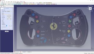
So I first had a look at some pictures of the 488 wheel, placed it as background and traced the outline to my liking – the first sketch of the right side is done.
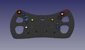
After the first draft, I also import the buttons and switches and place them at the according holes, adjusting the layout on the go.
As it turned out, there is still space left for 2 extra rotary encoders.
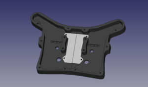
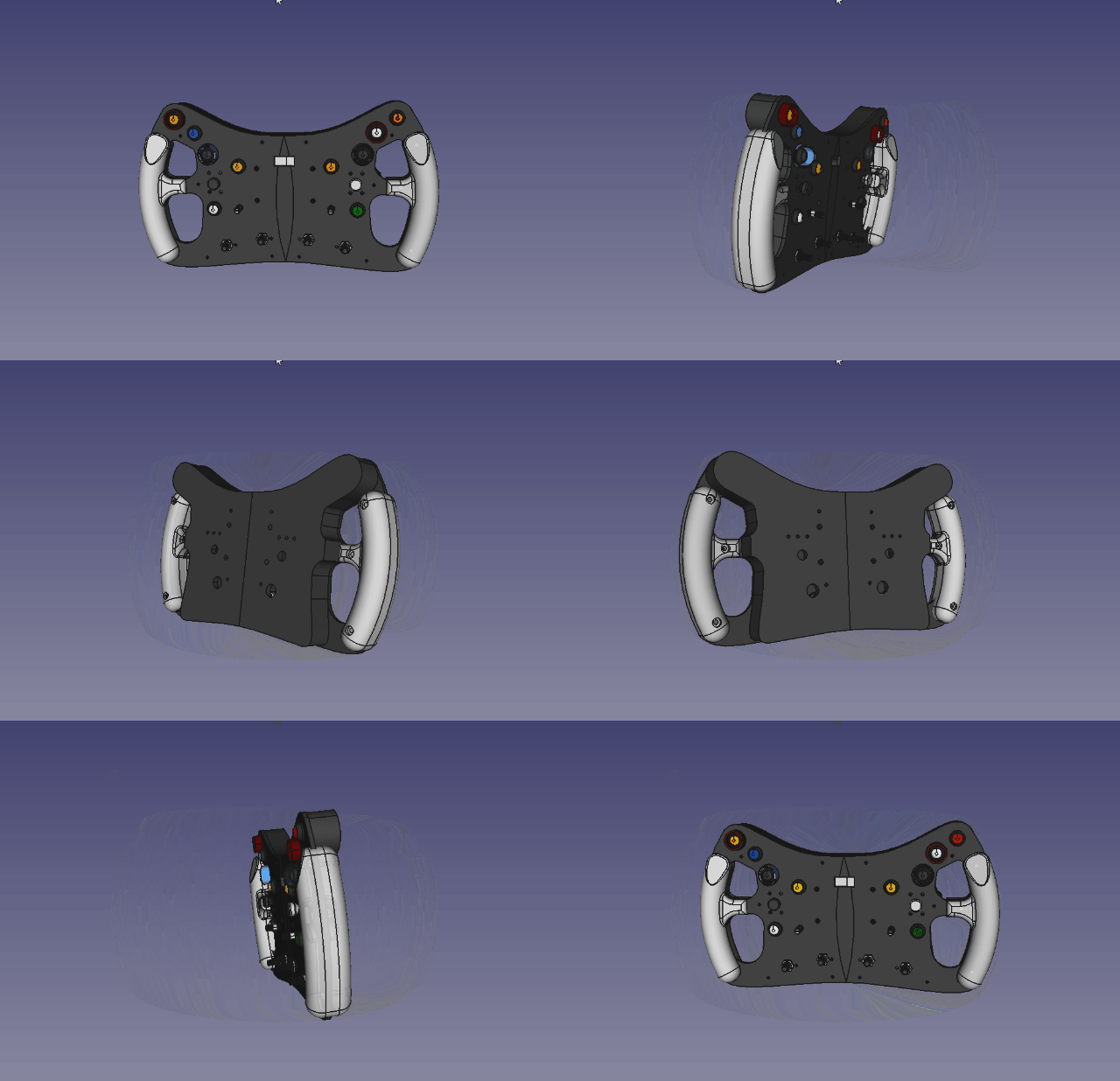
Once the wheelplate is finished, I take the sketch and use it to create the backhull (where the electronics and gear shifters would be placed) and I add a “PCBPlate” to mount the Arduino and input extender on.
And that’s how it looks when I’m done (for now *gg*)
Electronics/Firmware
While prototyping my DIY input console/macro keyboard I got quite some knowledge about using an Arduino ProMicro with many inputs and displays.
So my decision was easy – go the same route 😀
After the hardware prototype I finally know, how many inputs I will need on the Arduino:
- 2 for the shifters
- 10 for the buttons
- 14 for the 2 funkyswitches (up/down/left/right/down and 2 rotary directions)
- 6 for 2 rotary encoders
- 48 for the 4 12-position rotary switches
That’s 80 inputs in total, so the Joystick, I will be emulating, will have at least 80 buttons and 2 analogue inputs for the clutch paddles. But how do you get 82 inputs and an OLED display connected to a microcontroller with 18 I/O pins? 🙂
The answer is “i²c-IO-Extender”, in my case, the CJMCU-2317. It provides 16 additional I/O pins and communication with the Arduino is done over the i²c-bus which needs only 2 inputs on the Arduino side. It’s possible to use up to 8 of those extenders on one bus, so I will use 2 of them for most of the digital inputs. Even the OLED display is connected over i²c and doesn’t require more pins on the ProMicro.
The shifter paddles will be connected directly to 2 pins, since I’m planning to use digital hall sensors in it which are not supported on the 2317. All the other digital inputs (buttons, rotary encoders and funkyswitches) will be connected to the I/O extenders, one for each side. 5 buttons, 3 rotary inputs and 7 from one funky switch would be 15 pins used on each extender.
Although it would be possible to connect the 12-position-rotary-switches also to 3 more I/O extenders I opted for another solution to save space inside the housing.
When I was thinking about a solution for this, I rememberd “the old days(tm)” of the Logitech Sidewinder Joystick. It had a hat-switch, where all the positions of it where connected to just 1 analogue input with a resistor connected to each position. So when a position was pressed, checking the analogue value would tell you exactly, _which_ button has been pressed. That’s what I plan to do with my rotary switches.
I even found more infos on the internet, so I didn’t have to do the programming and fiddling all by myself:
https://www.instructables.com/Arduino-Rotary-Switch-One-Analogue-Input/
http://jespereklund.blogspot.com/2011/10/rotary-selector-switch-for-arduino.html
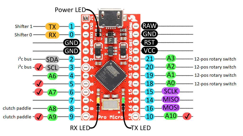
On this image it’s easy to see, how many pins I will use on the Arduino. Still 8 pins available – hmmmmm, already thinking about some LEDs on the wheel 🙂
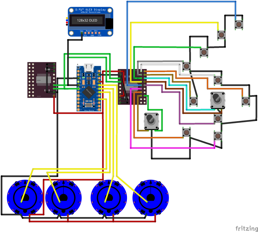
And that’s how the connections look like in Fritzing (only the right side is shown here, except the rotary switches.
The next phase in this project is the prototyping.

