Phase 3 – Building
After everything has been planned at the prototype looked like I intended it to I started with the final build.
Printing the both parts of the backhousing war the first thing done. This way I could use the parts for alignment errors in the prototype I could have missed – luckily everything fit perfectly.
To mount the frontplate to the housing I used M3 inserts which I put into the plastic using an old soldering station.

Once the fit checked out without errors I printed the paper template again but this time it got glued to a 4mm aluminium plate. Then I cut it out using my jigsaw and a metal cutting blade and drilled all the holes for buttons and switches.

I wanted to avoid any gaps between the frontplate and the grips so I left a bit more material while cutting.
Using 3D printed filing templates I could file the plate exactly to the shape of the grips.

After filing and deburring the front plate looks really nice.

Painting has been done using 2 coats of primer and 3 codes of matte black paint. While I was at it, the knobs for the switches also got their coats of paint.

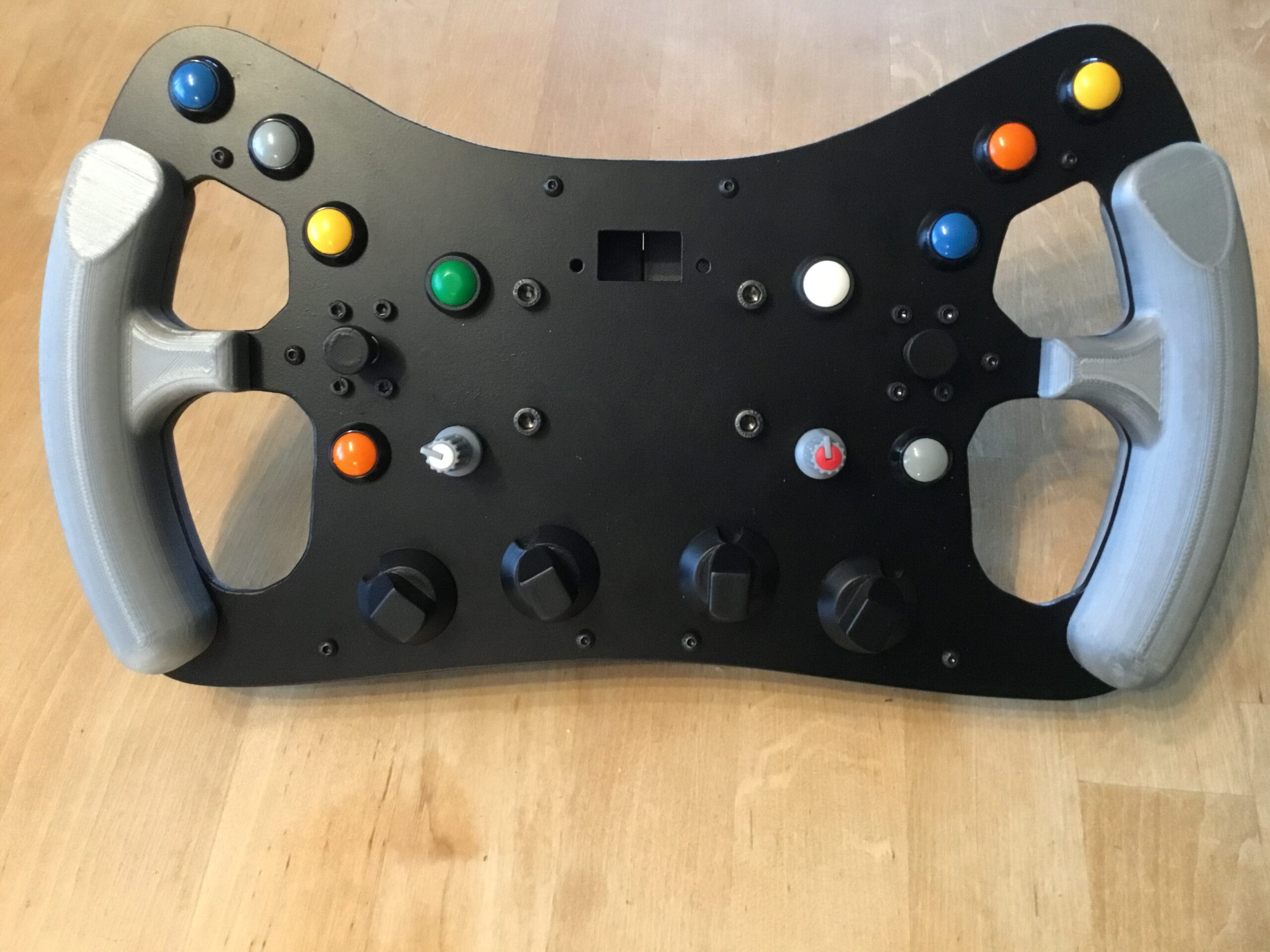
This week I put everything together, including the quickrelease, mounted it to the base and made my first test drive (still without shifters).
Compared to my current wheel the feeling while driving is much better due to the bigger diameter.
Since I didn’t like the feeling when pushing those cheap buttons I invested a bit of money and replaced them with real Otto P9 buttons.
Now the activating force is much higher and you can hear a loud “Click” to indicate, that the button has been pressed.
My next ToDos are to wrap the grips in leather, machine the knobs for the encoders out of aluminium and solder the electronics.
Looking nice, also very clever to use a template to file the plate!
Thx! It took me some time to realize the best way to file it as close as possible 😉